Density gap
Existing rack and airflow limits may not support the target accelerator heat load.
 Request a briefing ↗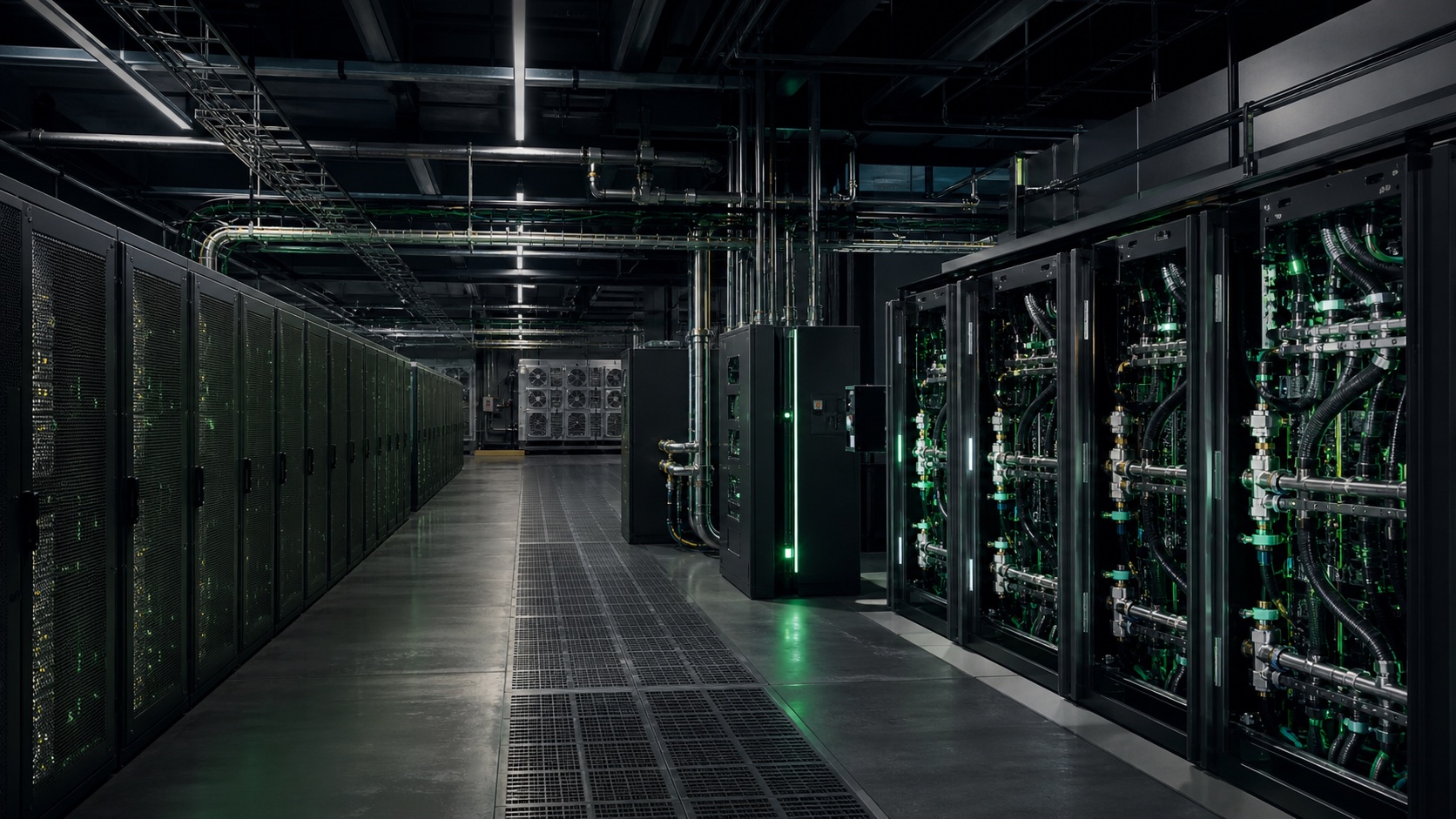
01 / AI-READY RETROFIT
IUNOVRA redesigns power, cooling, controls and heat rejection around the workload—reusing viable grid connections and assets while planning for operational continuity and creating a controlled path to high-density AI infrastructure.
THE NEED
Many existing facilities have valuable grid access, buildings and installed assets, but cannot support the intended AI workload without upgrades. Retrofit targets the limiting power, cooling and control interfaces before a new build is considered.
Existing rack and airflow limits may not support the target accelerator heat load.
Air-based systems can become inefficient or capacity-limited at higher heat densities.
Distribution, redundancy and controls must be redesigned around the target workload.
Modernisation must protect uptime, safety and operational continuity.
THE IUNOVRA RESPONSE
Power, cooling and controls must work together. IUNOVRA defines their interfaces and operating limits before equipment is selected.
WHAT YOU RECEIVE
Technical descriptions include reference designs and configuration options. The proposal separates demonstrated functions, integrations to validate and development work; only the agreed scope is included. Performance and service commitments follow the acceptance criteria.
DELIVERY MODEL
Workload, baseline and success criteria.
Site measurements and constraint mapping.
Detailed design and implementation roadmap.
Controlled works and staged commissioning.
Measured results and portfolio rollout decision.
TECHNICAL DEPTH
The engineering scope connects the workload, the live facility and the operating model. Every intervention is sized against measured constraints and commissioned against a defined baseline.
DIRECT-TO-CHIP RETROFIT
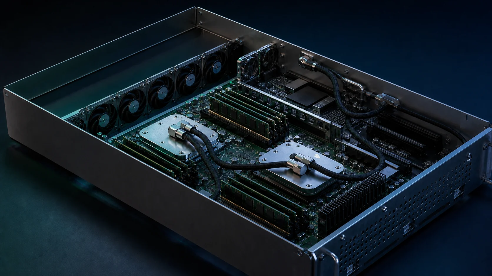
Compact sealed cold plates replace conventional processor heatsinks on compatible systems. Flexible coolant lines connect the processors to the wider cooling loop, with mounting, clearances and residual airflow validated for each server.
HOW RETROFIT WORKS
Cold plates are the starting point—not the whole solution. IUNOVRA integrates the server interface, cooling circuits, controls and heat rejection around the existing facility.
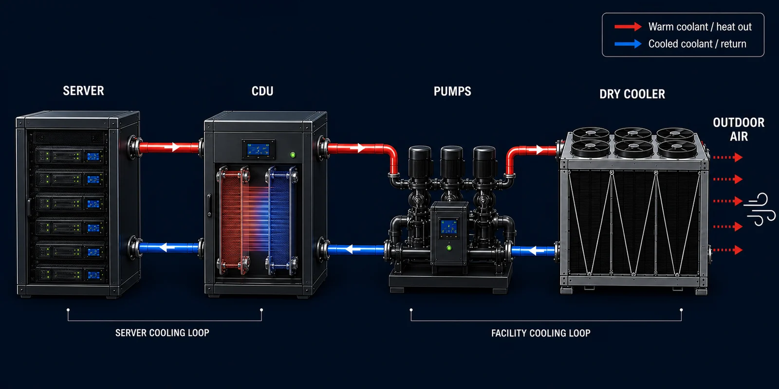
Liquid absorbs heat directly from compatible CPUs and GPUs, reducing the heat left for room air cooling.
The CDU regulates the server cooling circuit. In a liquid-to-liquid design, a heat exchanger separates it from facility coolant.
Pumps maintain the required flow and pressure in each circuit. Distribution and redundancy are engineered for the site.
A dry cooler transfers facility-loop heat to outdoor air where temperatures permit. Additional cooling depends on the climate and design.
Cooled fluid recirculates within each circuit. The server-side supply returns to the cold plates for the next cycle.
Two connected functions. Separate circuits where required. Heat passes through the CDU heat exchanger; server coolant and facility coolant do not need to mix.
Conceptual functional sequence—not a piping diagram. Equipment, temperatures and residual air cooling are validated per site.
Direct-to-chip loops, CDUs, manifolds, water quality, redundancy and heat rejection are engineered as one hydraulic system.
MV/LV distribution, UPS topology, busways, protection and rack delivery are checked against the target density and resilience class.
Space, structure, pipe routes, maintainability, fire strategy and live-site sequencing determine what can be reused and what must change.
Meters, sensors and BMS/DCIM integration establish the before-state and verify PUE, thermal stability, capacity and savings after commissioning.
Method statements, change windows, rollback plans, testing and operator training reduce risk while the facility remains in service.
The digital twin connects asset condition, capacity, energy and workload behaviour to continuous operational decisions.
VALUE + DECISION MODEL
The 700-rack, 13.3 MW reference asset is a screening example. It shows how different constraints change the intervention; it is not a forecast for a specific facility.
Use when grid and space are constrained. The value is lower facility energy per unit of IT load and released power headroom.
Use when spare or modular space exists and there is contracted demand for additional capacity. Reusing all released headroom increases compute capacity rather than preserving the full electricity saving.
This exceeds the original 13.3 MW envelope. Add power capacity or reduce the active rack/load requirement; higher rack density alone does not establish suitability for every AI workload.
Use only where power, permits, financing and committed AI demand support a phased high-density transformation.
HOW THE CASE IS VALIDATED
Use metered IT and facility load, utilisation, tariff, occupancy, contracted pricing and the full operating-cost base—not nameplate power alone.
Model PUE and capacity improvement by phase, with redundancy, climate, load profile and commissioning tolerances.
Separate gross energy savings, incremental revenue and full lifecycle costs. Confirm who pays for electricity and who retains savings under the customer contract.
Tie the project to customer demand, payment milestones, M&V methodology and post-commissioning performance.
Reference sensitivity: at a constant 7 MW IT load, improving PUE from 1.90 to 1.35 releases approximately 3.85 MW and yields about €4.7M in theoretical gross annual electricity savings. A further PUE sensitivity of 1.25 releases 4.55 MW and yields about €5.6M. Both use 8,760 operating hours and €140/MWh (€0.14/kWh), before CapEx, maintenance, other operating costs, financing and tax. These are site-dependent scenarios—not EBITDA or guaranteed savings.
CUSTOMER BENEFITS
EXISTING CONSTRAINTCooling limits constrain higher-power racks.
RETROFIT OPPORTUNITYEnable higher-density workloads where power, cooling and server compatibility allow.
EXISTING CONSTRAINTAir cooling carries a larger share of processor heat.
RETROFIT OPPORTUNITYMove heat directly into liquid and validate the effect on PUE and operating cost.
EXISTING CONSTRAINTAI upgrades can trigger a new-build discussion.
RETROFIT OPPORTUNITYRetain suitable buildings, grid connections and equipment; upgrade what constrains the workload.
EXISTING CONSTRAINTA major replacement can create operational disruption.
RETROFIT OPPORTUNITYSequence surveys, pilots and installation in controlled phases with agreed maintenance windows.
The opportunity is site-specific. Density, savings and installation timing are established through assessment and validation—not assumed from a universal multiplier.
Retrofit improves facility readiness; it does not turn existing CPUs into AI accelerators. Server compatibility, warranty, residual air cooling and the target compute configuration must be checked. Where site constraints outweigh reuse benefits, a POD or a new facility may be the better design.
WHY IT IS STRATEGIC
Brownfield modernisation can bring capacity online faster than a new-build cycle.
Verified energy savings may support green loans, leasing or performance-linked structures.
Retrofit opens the installed base for AI POD, storage, InfraMind and managed operations.
LET’S DISCUSS YOUR PROJECT