Thermal intensity
High-density accelerators need cooling matched to their heat load, including liquid cooling where required.
 Request a briefing ↗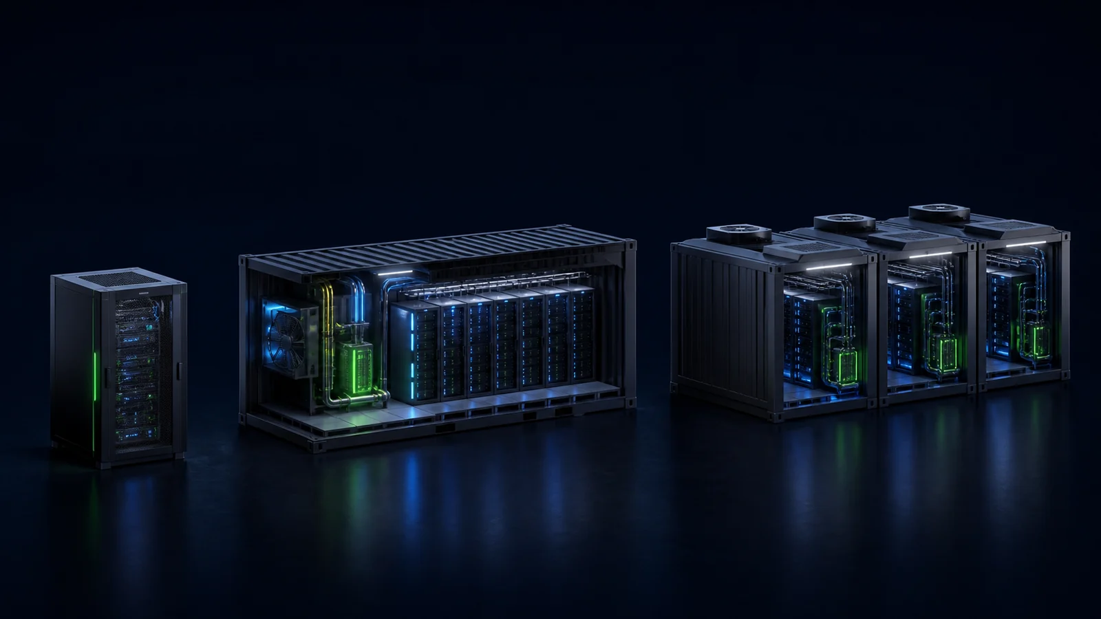
02 / AI POD
Deploy AI capacity where the workload needs it—from edge cabinets and containerised systems to high-density, multi-module data centres. AI POD brings compute, storage, networking, power and software into one engineered system, with cooling matched to the workload. Modular systems also form building blocks for distributed infrastructure.
THE NEED
Available power, cooling, latency and data-location requirements determine where AI can run. A POD brings these decisions into one engineered system, instead of leaving the customer to reconcile separate equipment and facility projects.
High-density accelerators need cooling matched to their heat load, including liquid cooling where required.
Compute, fabric, storage and facilities must perform as one validated system.
Sensitive data and latency-critical applications can require computing close to the source, with explicit access and operating policies.
The entry configuration must expand without forcing a complete redesign.
THE IUNOVRA RESPONSE
IUNOVRA configures the POD around the workload and deployment environment, using interoperable building blocks and InfraMind as the operating intelligence layer.
WHAT YOU RECEIVE
Technical descriptions include reference designs and configuration options. The proposal separates demonstrated functions, integrations to validate and development work; only the agreed scope is included. Performance and service commitments follow the acceptance criteria.
DELIVERY MODEL
Agree the workload, site readiness, interfaces and acceptance criteria.
Assemble the selected configuration and document integrated system tests.
Connect site services and verify performance, safety and operating readiness.
Provide operating documentation, responsibilities and agreed lifecycle support.
Use deployment evidence to replicate the design across additional sites.
TECHNICAL DEPTH
Explore the functional layers, then see how the POD connects to site power, cooling and networks.
INSIDE AN AI POD
Explore what each layer does and where the POD connects to the customer's infrastructure.
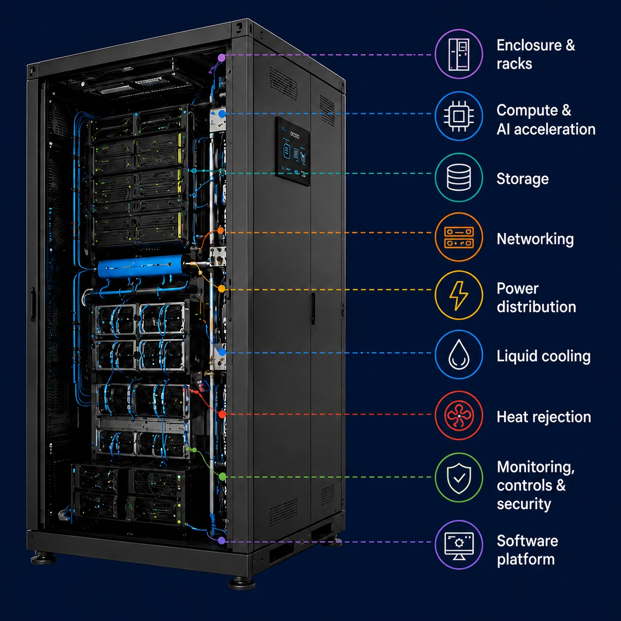
Labels identify functions, not exact equipment positions. Heat rejection may sit outside the cabinet; InfraMind connects the system as a software layer.
Cabinet, rack or modular enclosure with mounting, cable routing and service access. Environmental protection, physical access and internal layout are selected for the installation—not assumed to be identical at every scale.
CPU servers and GPU or other accelerator systems matched to inference, training, fine-tuning, analytics or HPC. Processor choice, memory and topology are balanced against the application and power envelope.
Local or pooled storage sized for throughput, capacity, checkpointing and protection. NVMe/SSD tiers and expansion enclosures are selected where required; encryption and data-integrity controls follow the agreed design.
Top-of-rack switching, Ethernet or InfiniBand where appropriate, fibre uplinks and a management network. Fabric bandwidth, segmentation and connections to customer networks are defined together.
Protection, intelligent power distribution units and metering connect the POD to the available electrical supply. UPS and generator capacity may be site-provided or separately scoped; they are not automatically included in every POD.
Where required, compatible cold plates, manifolds, connections, CDUs and pumps form the cooling architecture. Flow, temperature and leak monitoring are specified alongside residual air cooling and maintenance access.
A suitable facility cooling connection, dry cooler, heat exchanger or chiller arrangement completes the thermal design. Equipment location and capacity depend on climate, operating temperatures and site constraints.
Temperature, flow, pressure and leak sensing provide operational visibility. Humidity, smoke, access control, video and fire systems are selected as needed and coordinated with the site's safety and security provisions.
InfraMind brings telemetry and infrastructure context together for visibility, alerts and governed operations. Orchestration, optimisation, fleet management and integrations are defined by the deployment scope and supported interfaces—not assumed to be available in every configuration.
Explore InfraMind →THE POD + THE SITE
Standardised building blocks. Site-specific engineering. The same design principles connect an edge cabinet or a modular facility to the infrastructure around it.
Configured as one coordinated system
Utility feeds, UPS and batteries; generators where required.
Site cooling or dedicated CDUs, pumps, dry coolers or chillers.
External connections, customer networks and redundant routes as specified.
Fire protection, physical security, access and maintenance provisions.
Clear interfaces. Explicit responsibilities. Supporting equipment may be site-provided or delivered as dedicated modules—not automatically included in every POD. Capacity, resilience, site conditions and the operating model determine the final scope, commissioning tests and acceptance criteria.
VALUE + DECISION MODEL
One product family, configured at the scale the workload needs. Start with a bounded validation where appropriate, then expand after performance, site readiness and operating ownership are established.
Bring computing closer to users, industrial equipment and data sources when latency or locality matters.
Increase capacity through an integrated rack group, with isolation and service levels defined for the intended users.
Engineer the compute and cooling system together for training, fine-tuning or other intensive workloads.
Package larger capacity into a modular facility architecture. Grid connection, site works and resilience remain explicit design requirements.
HOW THE CASE IS VALIDATED
Evaluate delivered throughput, utilisation and availability—not hardware price in isolation.
Plan assessment, factory integration, logistics and site commissioning separately. On-site installation time is not the full order-to-operation lead time.
Model energy, cooling, support, refresh, software and expansion over the operating life.
Expand after performance, reliability, demand and operating ownership are demonstrated.
Configuration, density, deployment time and economics vary by accelerator generation, workload, facility interface, resilience level and supply availability. All figures require a customer-specific design and bill of materials.
CUSTOMER BENEFITS
Size capacity around suitable electrical and cooling infrastructure. Modular deployment can widen location choices, but does not remove grid or permitting requirements.
Run local inference and data-intensive applications near users, equipment and datasets when latency or data movement makes central processing less suitable.
Replicate validated configurations as workloads grow. Evaluate each addition against utilisation, service levels and full lifecycle costs.
Combine deployment location with access policies, data governance and defined support dependencies. Supported InfraMind integrations provide a common operating view across the estate.
A distributed estate is not automatically one high-performance GPU cluster. Tightly coupled training needs a validated low-latency, high-bandwidth fabric; local inference and independent jobs have different requirements. Every site still needs suitable power, connectivity, cooling and support.
WHY IT IS STRATEGIC
IUNOVRA combines its own design and software capabilities with selected partner technologies. Differentiation comes from engineering compute, storage, cooling and power around the workload—with coordinated interfaces and acceptance criteria, not a claim to manufacture every component.
PODs can connect to suitable existing facilities, with mechanical, electrical and network upgrades scoped explicitly. Open interfaces support customer and partner technology choices, subject to compatibility validation.
The delivery plan identifies engineering, assembly and testing responsibilities, partner facilities and support arrangements. Location and readiness are confirmed for the selected configuration.
Replicate validated PODs where site power, workload proximity and data policies support deployment. InfraMind connects supported sites through a common operational model, while each retains its own capacity, access and resilience boundaries.
LET’S DISCUSS YOUR PROJECT